September 23, 2026 Ixmore Art
When an installation moves from an artist’s sketch into a city square, waterfront park, or outdoor plaza within a commercial development, its ability to remain safe and intact for a decade often depends less on the concept itself than on the factory’s ability to engineer, fabricate, and reinforce the structure properly. Producing public art installations sits at the intersection of sculptural design and structural engineering, particularly when the work is large, irregularly shaped, and exposed to significant wind loads. A single flaw in a weld, connection, or material thickness can become a serious weakness under strong winds, temperature fluctuations, and repeated loading. Drawing on our experience serving commercial spaces and public landscape projects, this article provides a systematic overview of the key technical steps involved in turning large, irregular structures from drawings into finished installations.
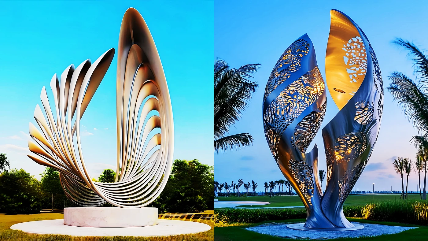
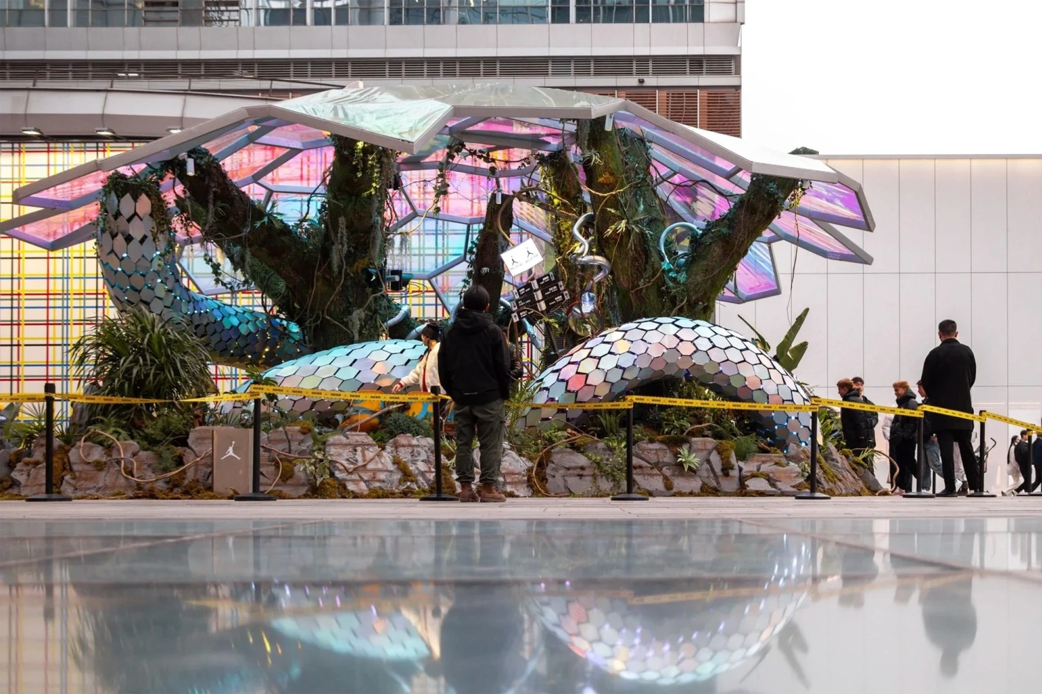
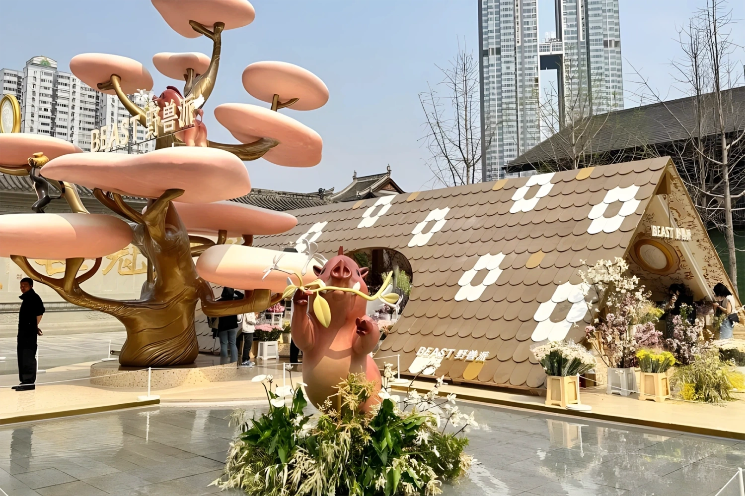
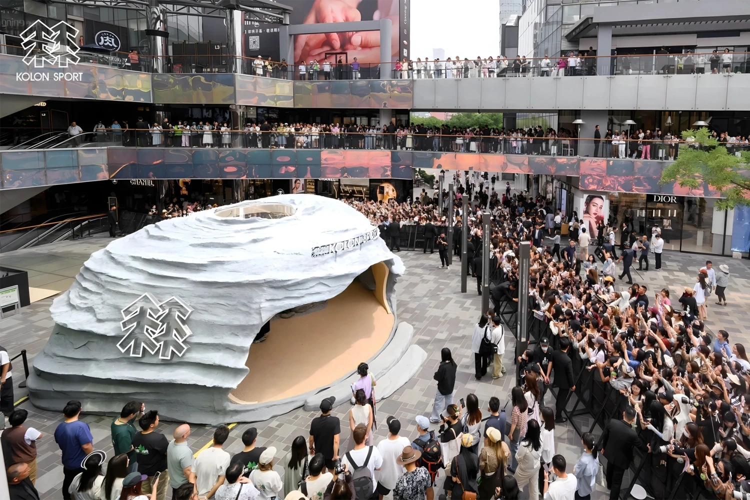
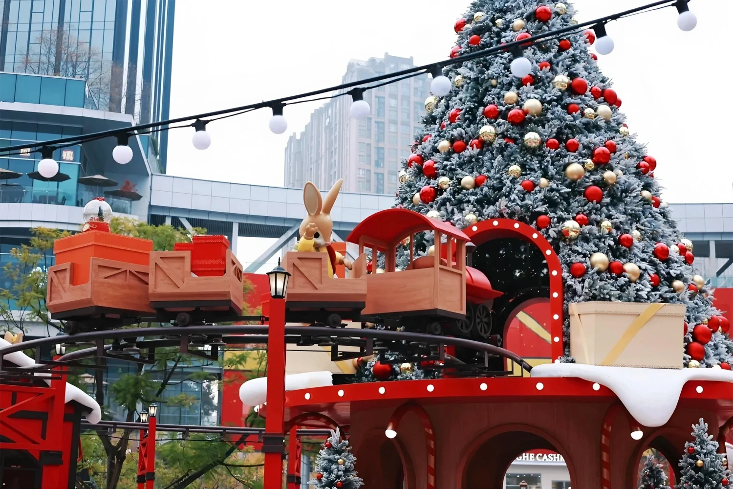
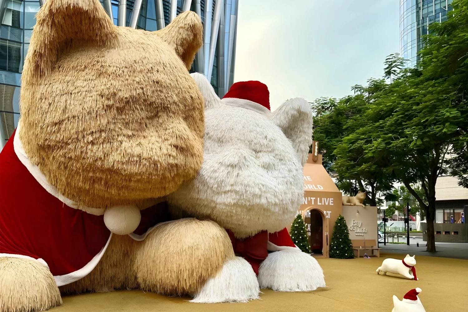
The fundamental difference between outdoor and indoor installations is exposure. A sculptural installation more than 6 meters tall must withstand its own weight, wind loads, thermal stresses, rain and snow, and, depending on the location, seismic activity. Complex structures are particularly challenging because they rarely rely on standardized beams, columns, or panels. Their free-form geometry means that load paths and stress conditions can vary across individual panels and structural members. When fabricating large, complex structures, three challenges are particularly important: forming curved surfaces in a cost-effective way; integrating the internal frame with the outer skin while maintaining reliable load transfer; and designing the base and foundation to resist long-term wind-induced overturning.
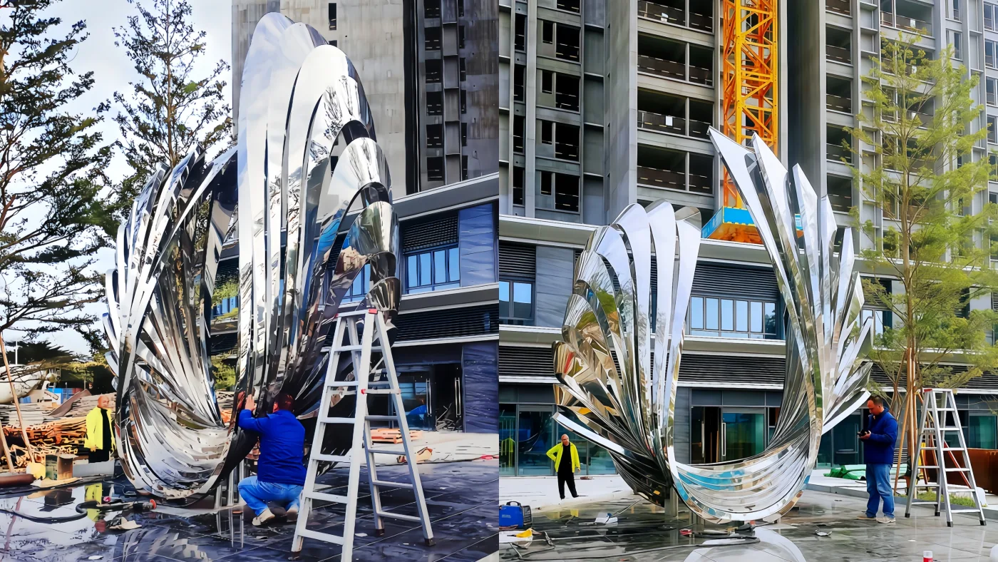
A well-established outdoor installation factory does not wait until the drawings are finalized before considering constructability. Instead, it gets involved at the concept stage to assess structural feasibility, identify potential fabrication issues, and prevent designs from reaching production only to be rejected as impractical or impossible to build.
For tall structures or installations with large wind-exposed surfaces, wind can be a more critical design factor than gravity. Industry practice commonly references load standards such as ASCE 7, with design wind pressure determined by factors including basic site wind speed, terrain exposure category, and structural shape coefficients. Engineering guidance also highlights that outdoor sculptures can experience substantial lateral forces in strong winds, much like a sail. For this reason, calculations should be based on the windward projected area—the so-called “sail area”—rather than simply the total surface area.
In the factory, the artist’s 3D model can be imported into FEA software to simulate stress distribution under critical load conditions. This helps identify high-stress areas, determine where reinforcement is required, and assess whether thin curved surfaces may buckle under wind suction. These calculations are not merely a formality; they can directly inform plate thickness, structural member sizes, connection details, and weld specifications. A mature fabrication process should incorporate the calculation model, wind-load mapping, and internal structural engineering into the project documentation rather than relying solely on verbal explanations.
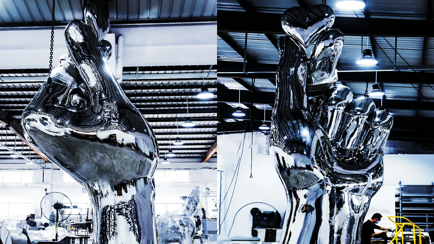
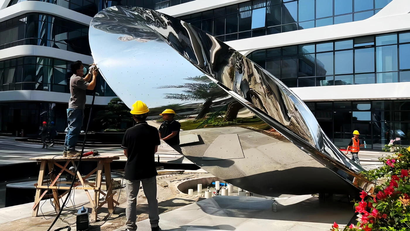
For metal outer skins made from stainless steel, aluminum, or weathering steel, freeform surfaces are typically developed by unfolding the 3D model and cutting the individual panels with laser or plasma CNC equipment, followed by forming, roll bending, or stretching as required. Each panel is pre-fitted and clearly numbered in the factory before being disassembled for transportation to the site. This “factory prefabrication, on-site assembly” approach is essential for large-scale installations because it improves transport efficiency while helping maintain dimensional and design accuracy during final assembly.
When an individual component exceeds transportation limits in length, width, or height, the structure must be divided into practical transport sections. Selecting the segment locations is an engineering decision: high-stress areas should be avoided, while on-site welds must remain accessible for welding, grinding, inspection, and subsequent surface finishing. Based on our experience reinforcing freeform structures, using thicker transition plates at joints is generally preferable to placing welds directly across abrupt changes in surface geometry. These transition areas are particularly susceptible to fatigue cracking caused by repeated wind-induced vibration.
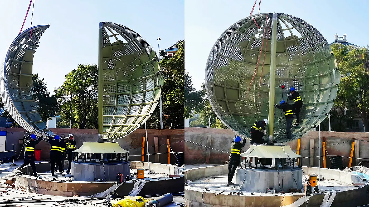
The outer skin provides the visible form, but the actual load-bearing system is the steel skeleton concealed inside. In many applications, hot-dip galvanized carbon steel or square and rectangular steel tubes are welded into a space-frame structure and connected to the outer skin through adjustable bolted nodes. Several details are critical to reliable node design: provide drainage and ventilation gaps between the outer skin and internal frame to prevent trapped moisture and crevice corrosion; use doubler plates at critical load-transfer nodes rather than simply increasing weld length; and place a non-shrink grout layer between the base plate and anchor bolts to ensure loads are transferred evenly into the foundation.
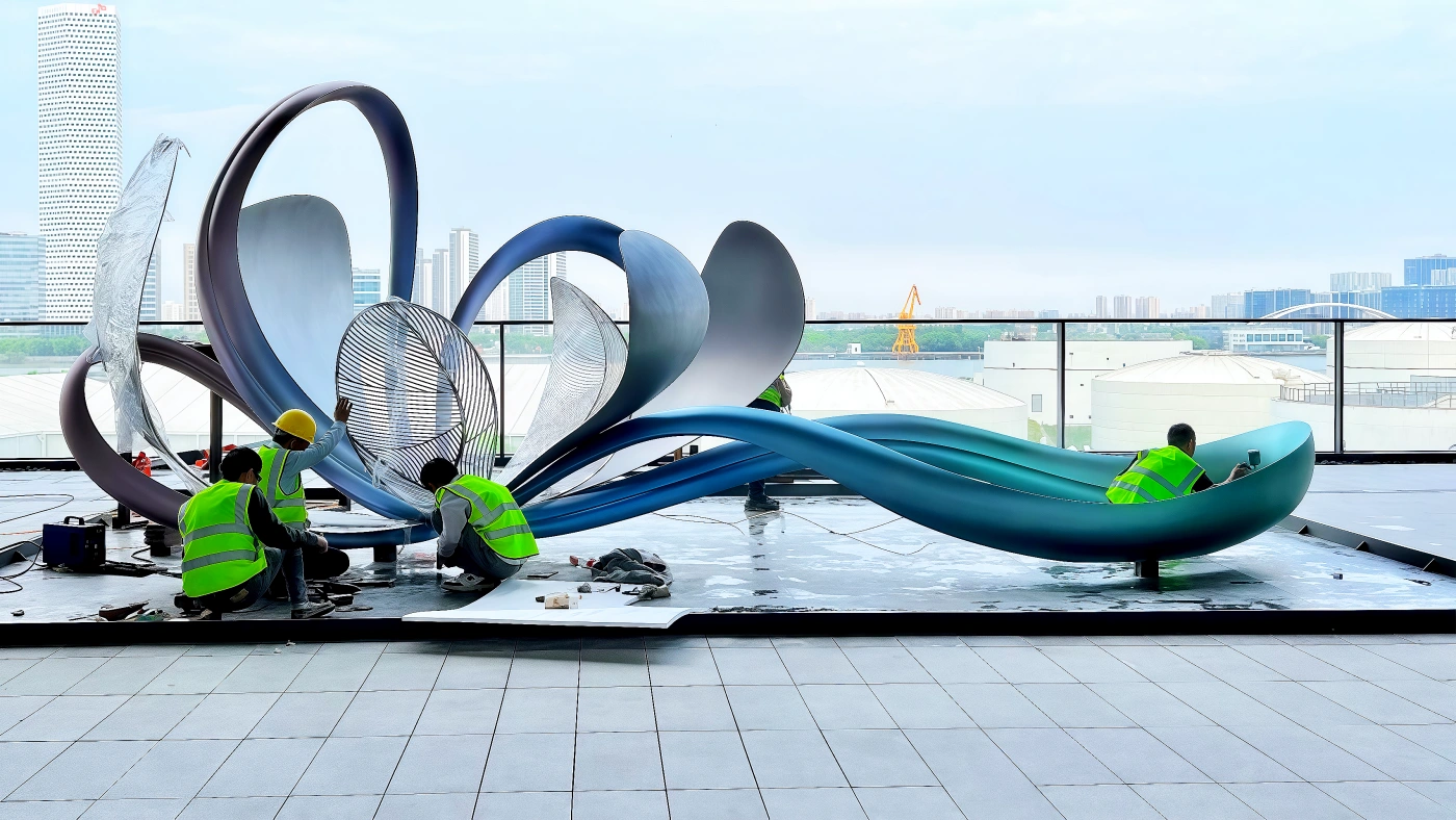
The service life of an outdoor installation depends heavily on both material selection and surface treatment. In coastal, highly polluted, or de-icing-salt environments, 316L stainless steel is often preferred because its molybdenum content provides greater resistance to pitting corrosion. For inland projects, 304 stainless steel with a fluorocarbon coating may be suitable. Projects seeking a naturally weathered appearance often use weathering steel (Corten), which develops a dense protective patina and generally does not require conventional paint maintenance. After welding, weld areas must be properly ground and polished to match the surrounding base metal. Otherwise, differences in the weld zone can leave it more vulnerable to premature corrosion over time. Mirror-polished surfaces require particular attention because untreated welds and heat-affected areas can be highly visible in direct sunlight.
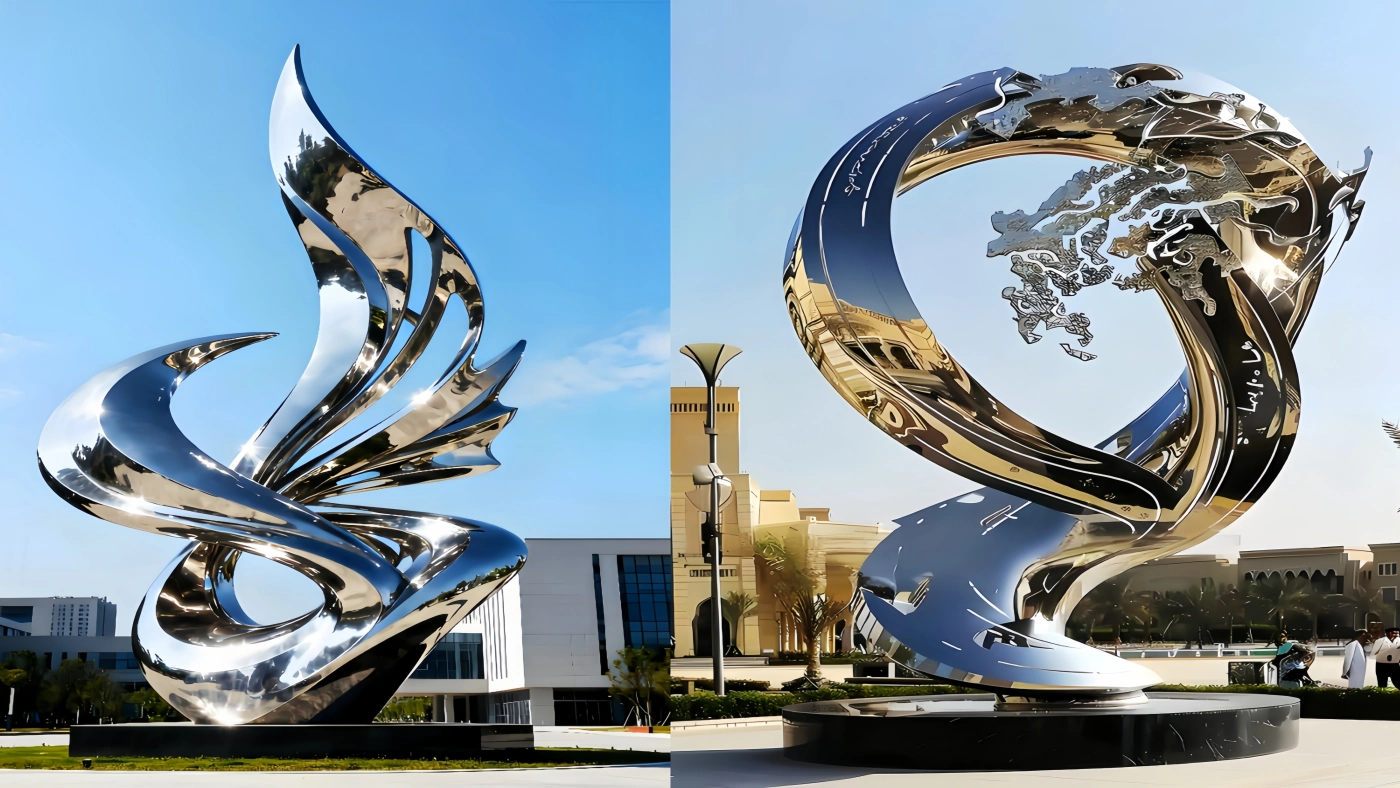
The “last mile” can be one of the most challenging stages for large installations. The factory should address three issues well in advance: first, provide a lifting plan showing lifting-lug locations and sling angles; second, divide the packaging according to transportation constraints and protect components against moisture, impact, and UV exposure; and third, coordinate with structural engineers to provide foundation embedment drawings and anchor-bolt layout diagrams. On-site anchoring commonly involves concrete piles or independent foundations, with embedded anchor bolts rigidly connecting the installation to the foundation to resist wind-induced overturning moments. For projects in seismic zones, the design should also account for the structure’s natural vibration period and the applicable earthquake load combinations.
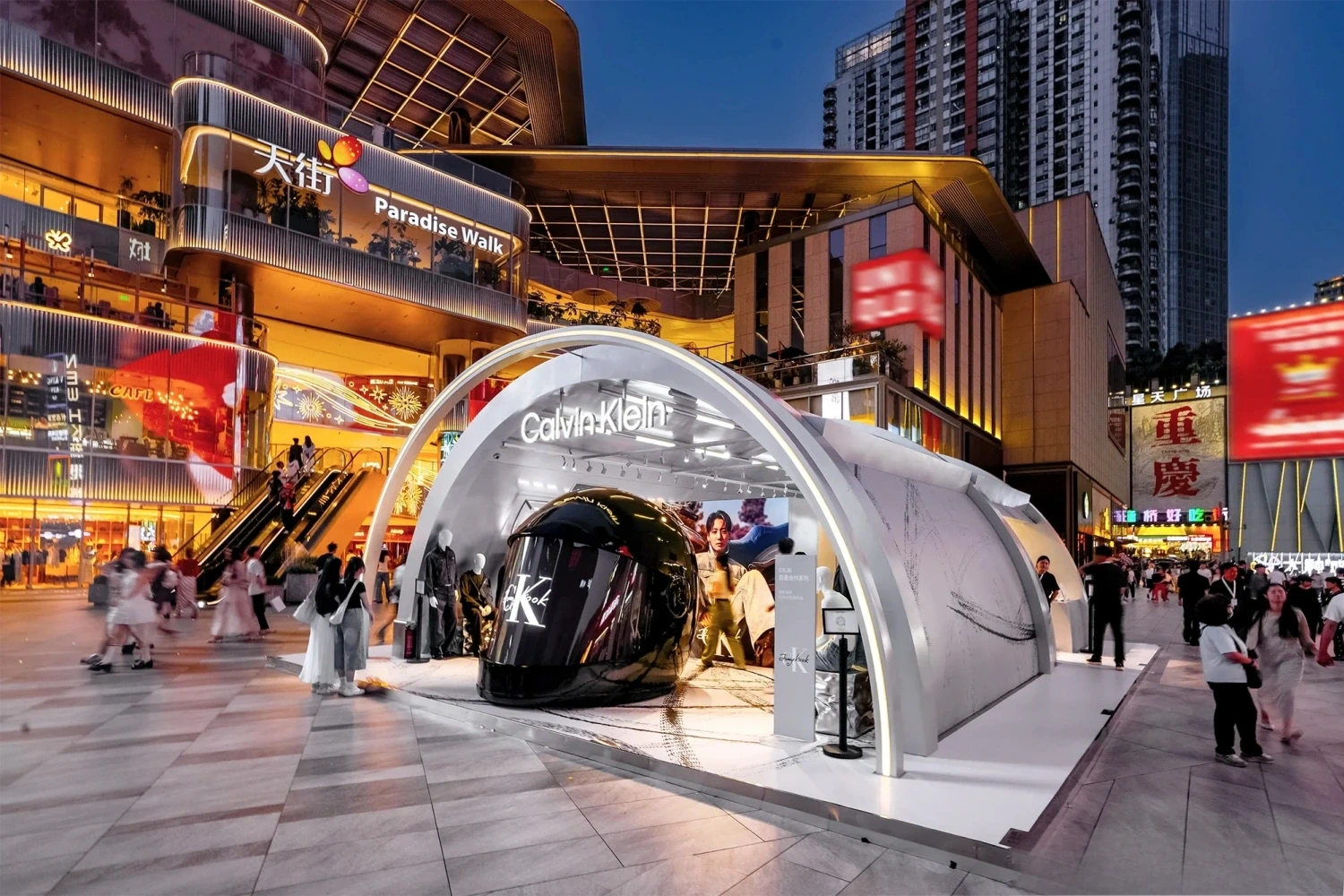
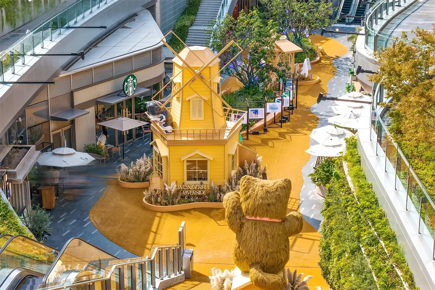
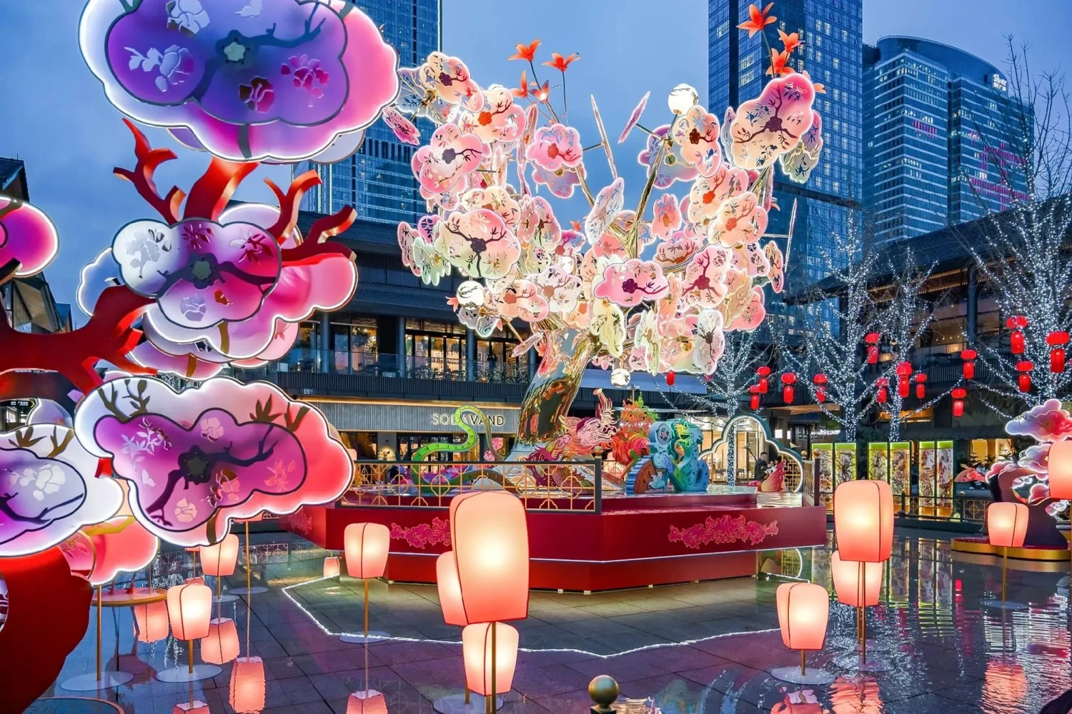
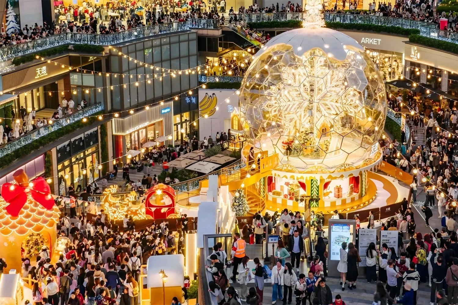
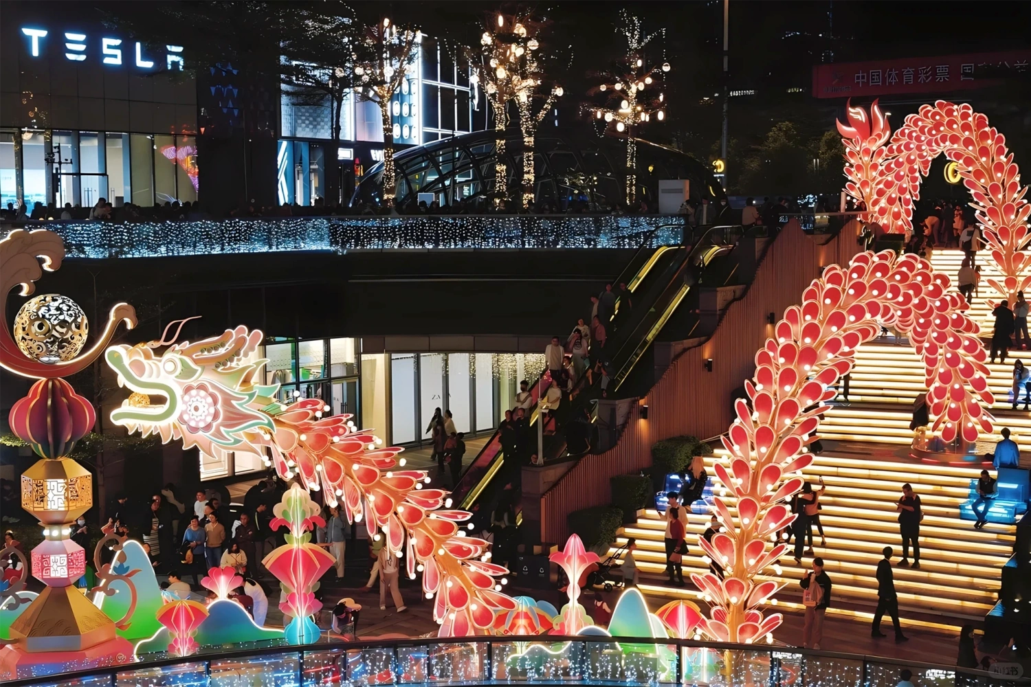
For designers, artists, developers, and general contractors, working with a factory that offers structural calculation capabilities, metal fabrication facilities, surface-treatment lines, and an on-site installation team means having a single accountable partner from concept through completion. We have long provided integrated custom installation services for shopping mall installations, festival and event environments, public art installations, and pop-up stores. Compared with dividing design, fabrication, and installation among three or four separate suppliers, an integrated model can provide tighter control over costs, schedules, accountability, and the final result. This end-to-end capability is also central to the way we approach public art and commercial space projects.
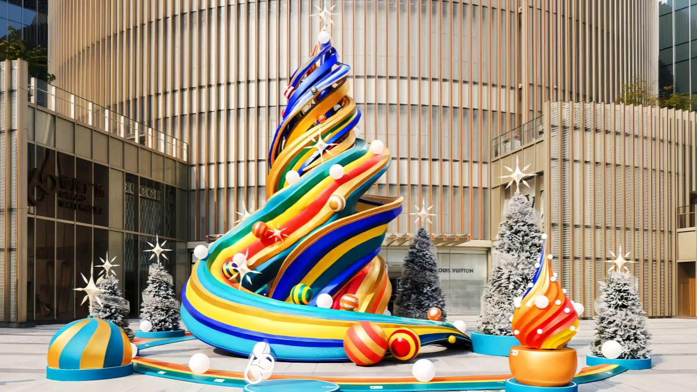
From freeform surface forming and wind-load verification to internal structural frames and on-site anchoring, every stage of producing a public art installation addresses the same fundamental question: how can an artistic concept remain safe, durable, and visually compelling in an outdoor environment for years to come? Our role goes beyond that of a conventional fabrication shop. We work as a technical partner that brings engineering discipline to artistic forms, providing the foundation needed to turn large, highly customized structures from drawings into durable installations in public spaces.
As a general guideline, installations taller than 3 meters, those with large wind-exposed surfaces, or those located in open areas or coastal high-wind zones should undergo structural calculations and foundation design before fabrication begins. Purely decorative indoor installations may require a simplified approach, but skipping structural review is not recommended for outdoor projects.
Stainless steel offers high strength and weather resistance, making it suitable for large structures and mirror-polished finishes. Aluminum is lighter and easier to form into large curves, but it generally has lower impact and wear resistance. For coastal environments, 316L stainless steel is often preferred. For inland projects requiring colored finishes, aluminum with a fluorocarbon coating may be considered.
Factories typically divide large installations into transportable, container-sized sections based on applicable container and road-transport limits. The sections are pre-assembled and numbered in the workshop, then reassembled on site according to the numbering system. Critical joints are marked and, where appropriate, test-fitted at the factory to improve dimensional accuracy and simplify on-site installation.
Mirror-polished stainless steel components are generally recommended to be cleaned and have their weld areas inspected every six months. Weathering steel typically requires minimal routine maintenance, while painted surfaces may require recoating every 5–8 years depending on UV exposure and local environmental conditions. The factory should provide a project-specific maintenance schedule in the handover documentation based on the actual installation environment.
Yes. We provide an integrated service covering 3D modeling, structural feasibility assessment, workshop fabrication, surface treatment, and on-site installation. We can also work with the artist or their designated structural engineer to develop calculation reports and installation drawings.
July 27, 2026
July 27, 2026
July 27, 2026
July 27, 2026
July 27, 2026
July 27, 2026
July 27, 2026
July 26, 2026
July 26, 2026
July 26, 2026
July 26, 2026
July 26, 2026
July 26, 2026
July 26, 2026
July 26, 2026
July 26, 2026
July 26, 2026
July 25, 2026
July 25, 2026
July 25, 2026